What you need to know about Cams.
#1 - the most common camshaft error made by people is to OVER cam the engine.
#2 - is selecting a cam that is not compatible for the RPM range that we plan to operate the engine in.
There are a number of things, which affect the cam’s performance.
Cylinder head flow rates: The cylinder heads must be able to flow enough air for the time that the valves are open.
Compression Ratio: Static compression ratio and cam choice should be considered as a system.
Intake: The intake must also flow enough air to support the cam and cylinder fill.
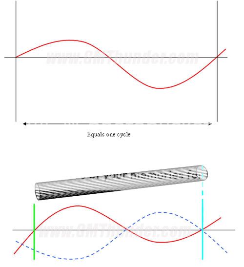
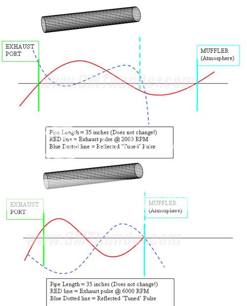
Exhaust pipes: The exhaust pipe must not only flow enough, they must be designed so that the reversion pulse is compatible with camshaft timing.
There is a little clue here for you sharpies and that is the word AIRFLOW. Airflow is everything and the camshaft is the controller of the airflow. It determines how much, when and how long. The result of all the camshaft specifications is where in the RPM band the motor will make the best power. Now one more thing before we dive in to the mystery and that is we need to understand our objective here. For the purposes of these articles I'm not interested in RACING motor but rather street motors and street motors need to develop TORQUE and they need to develop TORQUE in the 2500 to 4500 RPM range, as this is the range we most often operate the engine in (freeway cruising). There is a law of camshafts we need to keep in mind. - If you have it at the top, you will not at the bottom and if you have it at the bottom, you will not at the top. We cannot have it all. In a STREET motor, we do not need it at the top, we do need some at the bottom, but we really need mid-range. So here is where we are going to look for our torque. Now we also have to look at the bike we ride. A dresser is going to need more bottom end than a FXR due to the weight and wind resistance. All right, so now that we have all this behind us we can move on to the cam itself.
Intake Closing: The intake closing point has more effect on engine-operating characteristics than any of the other three opening and closing points. The earlier it occurs, the greater the cranking pressure. Early intake closing is critical for low-end torque and responsiveness and provides a broad power curve. It also reduces exhaust emissions while enhancing fuel economy. As RPM increases, intake charge momentum increases. This results in the intake charge continuing to flow into the combustion chamber against the rising far past BDC. The higher the engine's operating RPM, the later the intake closing should be to ensure all the charge possible makes it into the combustion chamber. Of course, closing the valve too late will create significant reversion. It is a fine balancing act. In a perfect world, the optimum intake closing point would occur just as the air stops flowing into the chamber. It would get the valve seated quickly and not waste time in the low lift regions where airflow is minimal and there is no compression building in the cylinder. It wouldn't be so fast the valve bounces as it closes, allowing the charge to escape back into the intake port and disturb the next charge. And in hydraulic street cam applications, it would insure that the closing ramps are not so fast that they result in noisy operation.
A late closing intake valve will yield poor compression and will cause poor performance over most of the entire RPM range.
A semi-late closing intake will have a good mid range and good top end but not the best.
An early closing intake (30-35 degrees) is what we like for a heavy bike because it will give an excellent bottom end performance and a good mid-range.
The intake valve closing point is intimately related to an engine's dynamic or "effective" compression ratio. Compression ratio is also dependent on cam duration.
A mild cam with an early intake valve closing point will work well at low RPM. However, at high RPM the intake valve will close before the maximum amount of air/fuel mixture has been drawn into the cylinder. As a result, performance at high RPM will suffer. If a high static compression ratio is used with a mild cam (i.e. and early intake valve closing point) then the mixture may end up being "over-compressed.” This will lead to excessive compression losses, detonation and could even lead to head gasket or piston failure.
On the other hand, an aggressive cam with a late intake valve closing point will work well at high RPM. However, at low RPM the intake valve will close too late for sufficient compression of the intake charge to occur. As a result, torque and performance will suffer. If a low static compression ratio is used with an aggressive cam (i.e. a late intake valve closing point) then the mixture may end up being "under-compressed.” Thus, a high performance cam with long duration should ideally be combined with a higher static compression ratio. That way the engine can benefit at high RPM from the maximized amount of intake charge afforded by the late intake valve closing, and still achieve sufficient compression of the mixture as a by-product of the dynamic compression ratio.
Intake Closing AGAIN!: The most important cam event. This sets the engine's effective RPM range, effective dynamic compression. An early closing (30 - 38 ABDC) = high dynamic compression, great low to mid RPM torque for a very broad power band, requires lower static compression (which means less stress and strain on the engine, less risk of heat damage and detonation, more reliability)....but engine RPMs are limited, the engine will "quit pulling" around 4800 RPM. As intake valve closing gets later (40-45) the power band moves up about 250 -300 RPM, narrows slightly unless more static compression is built in (e.g. thinner head gasket). Torque remains about the same, but due to higher RPMs, HP increases slightly. Throttle response off of idle drops slightly. Head temperatures increase slightly, making detonation a realistic risk, fuel management/tuning becomes even more critical. And exhaust pipe diameter, length, back-pressure designs become more influential. The engine will pull thru 5000 RPM. Closing the valve even later (+45 ABDC) shift the power band way up the RPM scale. Increased static compression is necessary to achieve any TQ/HP. Typically, it will exceed 12:1. Fuel management/tuning are very critical to reduce detonation and the risk of heat damage. Higher compression shortens the engine's life. Because this cam only functions well at higher RPMs, the other cam specifications can take advantage of this and be optimized for more power. What's lost is smooth idling and some usable power/torque at low to mid RPMs, crisp throttle responses from idle, engine heat issues become critical. Think about a bad-*** quarter mile drag bike: won't idle for crap, pops & snorts until the throttle is twisted nearly WFO, when it finally begins to roar - the engine is barely manageable - but damn, what a ride!
The intake closing point has more effect on engine-operating characteristics than any of the other three opening and closing points. The earlier it occurs, the greater the cranking pressure. Early intake closing is critical for low end torque and responsiveness and provides a broad power curve. It also reduces exhaust emissions while enhancing fuel economy. As RPM increases, intake charge momentum increases. This results in the intake charge continuing to flow into the combustion chamber against the rising far past BDC. The higher the engine's operating RPM, the later the intake closing should be to ensure all the charge possible makes it into the combustion chamber. Of course, closing the valve too late will create significant reversion. It's a fine balancing act. In a perfect world, the optimum intake closing point would occur just as the air stops flowing into the chamber. It would get the valve seated quickly and not waste time in the low lift regions where airflow is minimal and there is no compression building in the cylinder. It wouldn't be so fast the valve bounces as it closes, allowing the charge to escape back into the intake port and disturb the next charge; and in hydraulic street cam applications, it would insure that the closing ramps are not so fast that they result in noisy operation.
The most important timing event is the intake valve closing angle. The intake closing point determines the minimum RPM at which the engine begins to do its best work. The later the intake valves close, the higher the RPM must be before the engine gets "on the cam."
If you have one of the late closing cam designs installed, say one that closes the intake valves later than 40 degrees, then you cannot expect excellent performance at 2000 RPM. No carburetor adjustment, ignition adjustment or exhaust system can change this.
Intake Opening: Looking at the intake valve, its opening point is critical to vacuum, throttle response, emissions, and gas mileage. At low speeds, and high vacuum conditions, premature intake opening during the exhaust stroke can allow exhaust gas reversion back into the intake manifold, hurting the intake pulse velocity, and contaminating the fresh intake charge. A late opening intake gives smooth engine operation at idle and low RPM, and it ensures adequate manifold vacuum for proper accessory operation (assuming the other three valve opening and closing points remain reasonable). As RPM increase, air demand is greater. To supply additional air and fuel, designers open the intake valve sooner, which allows more time for the intake charge to fill the cylinder. With an early opening intake valve, at high RPM, the exiting exhaust gas also helps draw the intake charge thru the combustion chamber and out the exhaust - that's good for purging the cylinder of residual gas, but it also increases fuel consumption by allowing part of the intake charge to escape before combustion and can make for a rough idle.
Early usually means overlap, less throttle response at low to mid RPMs, rough idle, more emissions, poor fuel economy. However, by opening the intake valve early, we can slightly increase the volumetric efficiency of the engine...if the heads will flow any better. This is where stock heads fall short compared with ported heads. However - like cams, bigger is not always better when it comes to ported heads. Big ports and big valves will drop the intake and exhaust velocities, which can cause a host of problems, as well as a loss of volumetric efficiency. Most ported Twin Cam heads with stock diameter valves/seats, used with stock intakes and SE or K&N air filters usually flow their max CFM near 0.350" - 0.450" valve lift. Using a cam that has the intake valve open that far by the time the piston is at max velocity maintains the max intake charge velocity - which makes the best use of the momentum supercharging effect between idle and 3500 RPM. Using a cam with even more lift (+0.500") only reduces this effect - and power (along with adding more unnecessary wear and tear to the valve train). A stock, un-ported head has a very restrictive exhaust port, and therefore limits volumetric efficiency even further - making a cam with high lift even less effective. The thing to remember with cam timing is that the intake valve opens before TDC and closes after BDC.
Exhaust Opening: Overall, the exhaust valve opening point has the least effect on engine performance of any of the four opening and closing points. Opening the exhaust valve to early decreases torque by bleeding off cylinder pressure from the combustion that is used to push the piston down. Yet the exhaust has to open early enough to provide enough time to properly scavenge the cylinder. An early opening exhaust valve may benefit scavenging on high-RPM engines because most useful cylinder pressure is used up anyway by the time the piston hits 90-degrees before BDC on the power stroke.
Later exhaust valve opening helps low RPM performance by keeping pressure on the piston longer, and it reduces emissions.
Early opening exhaust - here we loose our entire bottom end and our mid range will be lazy what it will do is run hard on the top.
Semi-early opening exhaust. This timing will give us good cylinder scavenging which results in a cleaner cylinder mixture at high RPM the low end will suffer some but the mid range will be very good.
Late closing exhaust here we end up with a narrow RPM band the low end will be good as well as the mid-range but we will have an engine difficult to use.
Stock cams typically open the exhaust valve late (36 BBDC) to maximize the burn time and pass emission tests easier...but suffer from pumping losses because the piston has to work harder to mechanically push out the burnt gases. If the cam opens the exhaust valve a little sooner (40-43 BBDC), we can use blow-down (the expansion of burning A/F) to help scavenge the cylinder. This gets the burnt gases moving, reduces the piston effort, and decreases pumping losses...up too about 4000 RPM. However if the cam opens the exhaust valve too soon ( 45+ BBDC) the blow-down will bleed off much of the expansion pressure of the power stroke from idle thru about 2500 RPMs. The RPMs must be higher to overcome the time available for blow-down.
Exhaust Closing: Excessively late exhaust valve closing is similar to opening the intake too soon- it leads to increased overlap, allowing either reversion back up the intake, or the intake mixture to keep right on going out the exhaust. On the other hand, late closing events can help purge spent gasses from the combustion chamber and provide more vacuum signal to the intake at high RPM. Early exhaust valve closing yields a smoother operating engine. It does not necessarily hurt the top-end, particularly if it is combined with a later intake valve opening. As engine operating range increases, designers must move all the opening and closing points out to achieve earlier openings and later closings, or design a more aggressive profile to provide increased area under the curve without seat timing increases. Exhaust Valve Closing - usually between 4 (early) and 20 (late) deg ATDC. An early closing = less overlap, late closing = large overlap. Less overlap (exhaust valve closes at 4) makes it easier to pass a smog test, smooth idle, great fuel economy. A mild overlap (exhaust valve closes at 8-12) makes good low to mid RPM range power, better throttle response, fair fuel economy, slightly more emissions. And large overlap (exhaust valve closes at 13-20) allows a lot of intake charge dilution/loss (bad emissions), poorer fuel economy, rough idle, less throttle response from idle, and makes most of the power at higher RPMs. Note: the amount of overlap also depends on the cam's intake valve opening specifications.
Early exhaust valve closing yields a smoother operating engine. It does not necessarily hurt the top-end, particularly if it's combined with a later intake valve opening. As engine operating range increases, designers must move all the opening and closing points out to achieve earlier openings and later closings, or design a more aggressive profile to provide increased area under the curve without seat timing increases.
Lobe Centerline: Lobe Centerlines give you a relative perspective of how advanced or retarded a cam is in relation to top dead center (TDC). Harley cam profiles typically have an intake centerline from 98 to 108 degrees. An intake centerline of 98 is considered to be the most advanced and generally gives the most torque. A centerline of 108 will give power in the upper RPM range.
An exhaust centerline of 112 is the most advanced while the 102 is the most retarded. Again an advanced lobe will give power in the lower RPM range while the retarded lobe will have it's power range extended in the RPM range. For practical terms, most cams for Harley are in the range of 96-108 on intake and 112-102 on the exhaust.
Tailoring the valve opening and closing points on an actual camshaft is accomplished by varying the lobe centerline locations, changing the LSA, and refining the profile shape itself. Advancing the cam moves both the intake and exhaust in an equal amount, resulting in earlier valve timing events. Engines typically respond better with a few degrees of advance, probably due to the importance of the intake closing point on performance. For racing, advanced cams benefit torque converter stall, improve off-the-line drag race launches, and help circle-track cars come off the corner. Cam companies often grind their street cams advanced (4 degrees is typical), which allows the end-user to receive the benefits of increased cylinder pressure yet still install the cam using the standard timing marks. Increasing the intake lobe centerline from 104 to 106 degrees is considered retarding. All events will take place later in the engine cycle. Retarding the cam causes the intake valve to open and close later. This will reduce cylinder pressure which reduces the low speed performance of the engine.
Advancing the intake and retarding the exhaust (“closing up the centers”) increases overlap and should move the power up in the RPM range, usually at the sacrifice of bottom end power. The result would be lower numerical values on both intake and exhaust lobe centers.
Retarding the intake and advancing the exhaust (“spreading the centers”) decreases overlap and should result in a wider power band at the sacrifice of some top end power. This condition would be indicated by higher numerical values on both intake and exhaust lobe centers. By moving only one cam the results are less predictable, but usually it is the intake that is moved to change power characteristics since small changes here seem to have a greater effect.
Lobe Separation Angle: Lobe separation is the angle between the center bump of the intake lobe and its counterpart on the exhaust lobe. Think of it like the two points on a pair of scissors relative to the hinge in the middle. If the scissors are nearly closed, you can cut well as long as what you are cutting is thin. To cut thick stuff, you open wider, but have less leverage, so it can be harder to get the done. The same principle applies with separation on cam lobes. Typically, lobe separation for street cams runs between 97 and 108 (camshaft) degrees. The relationship between intake and exhaust is ground into the cam and can’t be altered by advancing or retarding the overall cam timing.
As a guideline, if the rest of the numbers are comparable, a cam with a lobe that is less separate (for example, 98 to 103 degrees) will offer a broader spread of power and tend to produce power at the low end, while wide lobes make for a more “cammy” cam, coming on harder and later in the game. Lobe Separation Angles (LSA) of 100-103 degrees tend to produce power at the low end.
LSA and Lift affect the "sound" and idle quality. Generally, smaller lobe separation angles cause an engine to produce more mid-range torque and high RPM power, and be more responsive, while larger lobe separation angles result in broader torque, improved idle characteristics, and more peak horsepower.
A “tight” lobe separation angle of 103 degrees or less creates more valve overlap, which helps create that lumpy idle characteristic of big camshafts. The tighter LSA’s are, the more likely problematical exhaust reversion into the intake will occur. Put simply, we can say that a tight LSA cam produces a power curve that is, for want of a better description, more "punchy." At low RPM when off the cam, it runs rougher, and it comes on the cam with more of a "bang." Narrow LSA’s tend to increase mid-range torque and result in faster revving engines. Generally, smaller lobe separation angles cause an engine to produce more mid-range torque and high RPM power, and be more responsive. Typically, however, small lobe center numbers (more overlap) equates to more mid-range power at the expense of top-end power. Probably the most significant factor to the engine tuner though is a tight LSA’s intolerance of exhaust system back-pressure. Remember, during the overlap period both valves are open. If there’s any exhaust back-pressure or if the exhaust port velocities are too low it will encourage exhaust reversion. A cam with 102 degrees of lobe separation angle will have more overlap and a rougher idle than one with 108 degrees, but it'll usually make more mid-range power. A tighter lobe has more overlap. A tighter centerline starts torque curve sooner, and doesn't give a wide power band. A wider lobe doesn't start the torque curve sooner, but it continues to make torque longer and has a broader power band.
Wide LSA’s result in wider power bands and more peak torque at the price of somewhat lazier initial response. Larger lobe separation angles result in broader torque, improved idle characteristics, and more peak horsepower. A wider lobe doesn't start the torque curve sooner, but it continues to make torque longer and has a broader power band. A street engine with a wide LSA has higher vacuum and a smoother idle. Big numbers (less overlap) will give more top end, sacrificing mid-range. A cam on wide centerlines produces a wider power band. It will idle smoother and produce better vacuum, but the price paid is a reduction in output throughout the working RPM range.
Narrow LSA (98-103)
Moves Torque to Lower RPM
Increase mid-range Torque
Increases Maximum Torque
Faster revving engine and more responsive
Narrow Power band
Builds Higher Cylinder Pressure
Increase Chance of Engine Knock
Increase Cranking Compression
Increase Effective Compression
Idle Vacuum is Reduced
Idle Quality Suffers (lumpy idle characteristic)
Open Valve-Overlap Increases
Closed Valve-Overlap Increases
Decreases Piston-to-Valve Clearance
Wide LSA (104-108)
Raise Torque to Higher RPM
Reduces Maximum Torque
Broadens Power Band
Lazier initial response
More peak Horsepower
Reduce Maximum Cylinder Pressure
Decrease Chance of Engine Knock
Decrease Cranking Compression
Decrease Effective Compression
Idle Vacuum is Increased
Idle Quality Improves
Open Valve-Overlap Decreases
Closed Valve-Overlap Decreases
Increases Piston-to-Valve Clearance
Overlap: The objective of overlap is for the exhaust gas which is already running down the exhaust pipe, to create an effect like a siphon and pull a fresh mixture into the combustion chamber. Otherwise, a small amount of burned gasses would remain in the combustion chamber and dilute the incoming mixture on the intake stroke. Duration, lift and LSA combine to produce an "overlap triangle". The greater the duration and lift, the more overlap area, LSA’s remaining equal. Given the same duration, LSA and overlap are inversely proportional: Increased LSA decreases overlap (and visa versa). More overlap decreases low RPM vacuum and response, but in the mid-range, overlap improves the signal provided by the fast moving exhaust to the incoming intake charge. This increased signal typically provides a noticeable engine acceleration improvement.
Less overlap increases efficiency by reducing the amount of raw fuel that escapes thru the exhaust, while improving low-end response due to less reversion of the exhaust gasses back up the intake port; the result is better idle, stronger vacuum signal and improved fuel economy. Due to the differences in cylinder head, intake and exhaust configuration, different engine combos are extremely sensitive to the camshaft’s overlap region. Not only is the duration and area of the overlap important but also its overall shape. Much recent progress in cam design has been due to careful tailoring of the shape of the overlap triangle. According to Comp Cams, the most critical engine factors for optimizing overlap include intake system efficiency, exhaust system efficiency, and how well the heads flow from the intake toward the exhaust with both valves slightly open.
Camshaft overlap duration less than 30 degrees tends to produce good low end power.
Overlap amounts to the time the intake and the exhaust valves are both open. When you get it right, overlap helps draw in the intake charge, but excessive amounts actually reduce power by letting intake charge escape out the open exhaust valve. Lots of overlap virtually guarantees a cam won’t work well at low RPM, regardless of how strong it is wide open. Camshaft overlap duration of less than 30 degrees tends to produce good low end power.
Increased overlap equates to reduced idle quality, vacuum, and harsher running prior to coming up on the cam. Lots of overlap works great at high RPM because more intake charge manages to cram itself into the cylinder, but lots of overlap will also make the engine run badly at low RPM, as exhaust gas manages to make its way back up the intake manifold, diluting the incoming air/fuel charge, and depositing soot on the intake runners, carburetor, etc. Cams with a lot of overlap tend to cause rougher idling because of the lack of vacuum they create in the manifold.
Overlap (lots of duration and tight lobe-separation angles) decreases cylinder pressure, especially at low RPM, which allows an engine to run a higher compression ratio and still work on pump gas. High cylinder pressure, which is caused partly by a high compression ratio, is what makes an engine detonate on pump gas. Decreasing the cylinder pressure by adding duration is just like taking compression out of the engine, but mostly only at low RPM.
Duration: Duration has a marked affect on a cam's power band and drive-ability. Higher durations increase the top-end at the expense of the low end. A cam's "advertised duration" has been a popular sales tool, but to compare two different cams using these numbers is dicey because there's no set tappet rise for measuring advertised duration. Measuring duration at 0.053-inch tappet lift has become standard with most high-performance cams. Most engine builders feel that 0.053” duration is closely related to the RPM range where the engine makes it's best power. When comparing two cams, if both profiles rate the advertised duration at the same lift, the cam with the shorter advertised duration in comparison to the 0.053” duration has a more aggressive ramp. Providing it maintains stable valve motion, the aggressive profile yields better vacuum, increased responsiveness, a broader torque range, and drivability improvements because it effectively has the opening and closing points of a smaller cam combined with the area under the lift curve of a larger cam. Engines with significant airflow or compression restrictions like aggressive profiles. This is due to the increased signal that gets more of the charge through the restriction and/or the decreased seat timing that results in earlier intake closing and more cylinder pressure. Big cams with more duration and overlap allow octane-limited engines to run higher compression without detonating in the low to mid-range. Conversely, running too big a cam, with too low a compression ratio leads to a sluggish response below 3,000 RPM. Follow the cam grinders recommendations on proper cam profile-to-compression ratio match-up.
Duration generally ranges from 220 degrees for a torquey bottom-end cam all the way to 295 degrees for a of “top end rush,” typically measured at 0.053 inch lift.
As a general rule, lower-duration cams in the neighborhood of 210 to 200 degrees at 0.053 work best for stock-type replacement cams. Stepping past 220 degrees of duration (at 0.053) places the cam into the bolt-on, mid-range style category. These cams work well with the stock compression, intake and exhaust. Cams with 240-plus degrees of duration or more are beginning to step into the performance arena and generally work better with other induction, compression, and exhaust modifications. Duration has a marked affect on the cams power band and drivability.
Higher durations increase the top-end at the expense of the low end. As a general rule, cams with 220-235 degrees of duration tend to produce good low end torque. Cams with 235-250 degrees of duration tend to work best in the mid-ranges and cams over 260 degrees work best for top end power.
It is important to remember here that the duration values given are to be used as a general rule and that increasing the duration will have an effect on the idle characteristics and overall drivability.
Long duration, late intake closing cam designs are necessary to drag the last bit of power out of an engine. Unfortunately, these same cams can perform poorly under more normal riding conditions. In the quest for maximum power output, many-too-many Harley owners choose a late closing, high-RPM cam for their engine. The problem with such choices is that the engine seldom spends time in the RPM range favored by such cams.
Lift: Another method of improving cam performance is increasing the amount of lobe lift. Designing a cam profile with more lobe lift results in increased duration in the high-lift regions where cylinder heads flow the most air. Short duration cams with relatively high lift can provide excellent responsiveness, great torque, and good power. But high lift cams are less dependable. You need the right valve springs to handle the increased lift, and the heads must be set up to accommodate the extra lift. There are a few examples where increased lift won't improve performance due to decreased velocity through the port; these typically occur in the race engine world (0.650- to 1.00-inch valve lift). Some late model engines with restrictive throttle-body, intake, cylinder head runner and exhaust flow simply can't flow enough air to support higher lift.
Cam (or lobe) lift is the maximum height or distance that the lifter or follower is raised off the cam. More lift generally means better top-end power, but you’ll sacrifice bottom-end response. In addition, cams with high lift typical put more wear and tear on the valve train.
For street bikes, lift figures are best kept at or below 0.500 inch, simply because, with the right cam, you can still get all the power you can use, but you won’t be needing a new valve train every 20,000 miles. Sure, with the right cylinder head/piston combination, lifts in the mid 0.500 inch range, even perhaps encroaching on 0.600 inch can work, but pushrods flex, geometry goes AWOL, and the extra benefits of the lift are quashed by the limits of flow through the ports (particularly the exhaust port), so why bother? Mega lift is more valuable to drag racers who re-engineer the whole plot any way.
The other potential problem with increasing the cam lift is that there is only so much clearance between the piston and the valve. The other problem associated with elevated lift numbers is spring fatigue. The greater the lift the farther the spring will have to expand and contract during each rotation of the cam. Cams with more lift are much harder on springs, causing a reduction in spring life.
Symmetrical cams: This simply means that the cam lobe is the same on both sides. This means that the valve opens and closes at the same rate.
Asymmetric Lobes: In the past, both opening and closing sides of a cam lobe were identical. Most recently, designers developed asymmetrical lobes, wherein the shape of the opening and closing sides differ. Asymmetry helps optimize the dynamics of a valve train system by producing a lobe with the shortest seat timing and the most area. The designer wants to open the valve as fast as possible without overcoming the spring's ability to absorb the valve train's kinetic energy, then close the valve as fast as possible without resulting in valve bounce. There are many different theories about how to design the most aggressive, stable profile. Hydraulic lifters can provide quiet valve train operation only if the closing velocity is kept below a certain threshold. However, the opening velocity can be higher and still provide quiet operation. Almost all modern hydraulic profiles have some symmetry.
Here the lobes differ from the opening side to the closing side. This allows the cam grinder to open the valve a one speed and close it at another. Here is where some cams are quite and some noisy. If the grinder has chosen to set the valve down slowly on the seat it will be a quitter cam than if the grind lets the valve down too quickly. Single pattern cams In the case of single pattern cams both the intake and exhaust lobe are the same. A cam can be asymmetrical and single pattern or symmetrical and single pattern. Dual pattern cams have different profiles on the intake and exhaust lobes. A cam of this type can be any combination of asymmetrical or symmetrical of profiles.
Camshaft Noise: Camshaft noise is partly from cam shaft ramp design and partly mechanical noise from end play and excess gear lash. Camshaft noise and gear lash is dictated by the cam support plate. When the teeth of the gears mesh, they produce annoying whine if they mesh too tightly and a clackety clatter if they’re too loose. However, these gears also expand slightly when the engine is at operating temperature and then return to their original size when the engine cools down, which is why it’s impossible to get them to be quiet all the time.. Throw in loose manufacturing tolerances on the cam support plate and you have a complicated issue on your hands, which is why Harley replaced gear driven cams with chain driven cams.
Effect of Compression Ratio on Camshaft Selection: It is instructive to remember that the static compression ratio that your engine displays on paper does not translate directly to higher cylinder pressures. The cylinder pressure (prior to ignition) during engine operation is dependent on what can loosely be called "dynamic or effective compression ratio". The pressure is greatly affected by the timing of your valve events - i.e. cam duration and timing. Specifically, the intake valve closing point is intimately related to an engine's dynamic, or "effective" compression ratio.
But we just learned on static compression ratio is directly related to stroke. In principle, the piston cannot compress the mixture until the intake valve closes. Thus if the intake valve closes when the piston has already moved quite some distance up the bore, then the amount that the intake charge will be compressed is reduced. The "effective compression stroke" has been reduced. Does this mean that when an engine is operating that the dynamic compression ratio is lower than the static compression ratio? Well yes and no.
An engine with a performance cam operating at low RPM will suffer a loss of torque due to the fact that the effective compression ratio is reduced by the late intake valve closing point. However, as the RPM increases "inertia supercharging" becomes important. At high RPM's the intake charge is is moving into the cylinder at high velocity. As such it has a lot of inertia and will continue moving into the cylinder past BDC, even though the piston has changed direction and is now moving up the bore (towards the incoming charge). Ideally the intake valve will close just before the incoming air stops and reverses direction. This guarantees that the maximum amount of air/fuel mixture has been drawn into the cylinder prior to ignition. When this happens an engine is said to have "come on the cam". In order to ensure that the mixture is still compressed sufficiently over the reduced effective compression stroke it is necessary to increase the static compression ratio. This is why high performance engines with aggressive camshafts also tend to have high static compression ratios.
Bottom line: Static compression ratio and cam choice should be considered as a system.
A mild cam with an early intake valve closing point will work well at low RPM. But at high RPM the intake valve will close before the maximum amount of air/fuel mixture has been drawn into the cylinder. As a result performance at high RPM will suffer. If a high static compression ratio is used with a mild cam (i.e. and early intake valve closing point) then the mixture may end up being "over-compressed". This will lead to excessive compression losses, detonation and could even lead to head gasket or piston failure.
On the other hand, an aggressive cam with a late intake valve closing point will work well at high RPM. But at low RPM the intake valve will close too late for sufficient compression of the intake charge to occur. As a result torque and performance will suffer. If a low static compression ratio is used with an aggressive cam (i.e. a late intake valve closing point) then the mixture may end up being "under-compressed". Thus a high performance cam with long duration should ideally be combined with a higher static compression ratio. That way the engine can benefit at high RPM from the maximized amount of intake charge afforded by the late intake valve closing, and still achieve sufficient compression of the mixture as a by-product of the dynamic compression ratio.